The bus they connect to runs at 1 Mbps, carries Manchester-encoded data on a dual-redundant pair, and works half-duplex on a command-response model. One bus controller talks to as many as 31 remote terminals over a 70 to 85 ohm shielded twisted pair. Your transceiver and transformer are how any single terminal reaches that wire.
TL;DR Quick Answers
MIL-STD-1553 Transceivers and Transformers
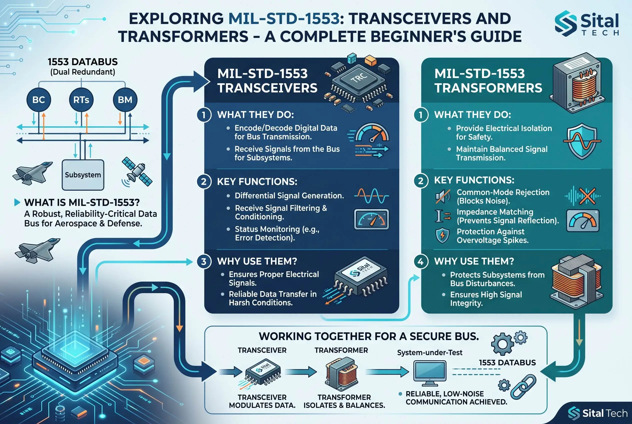
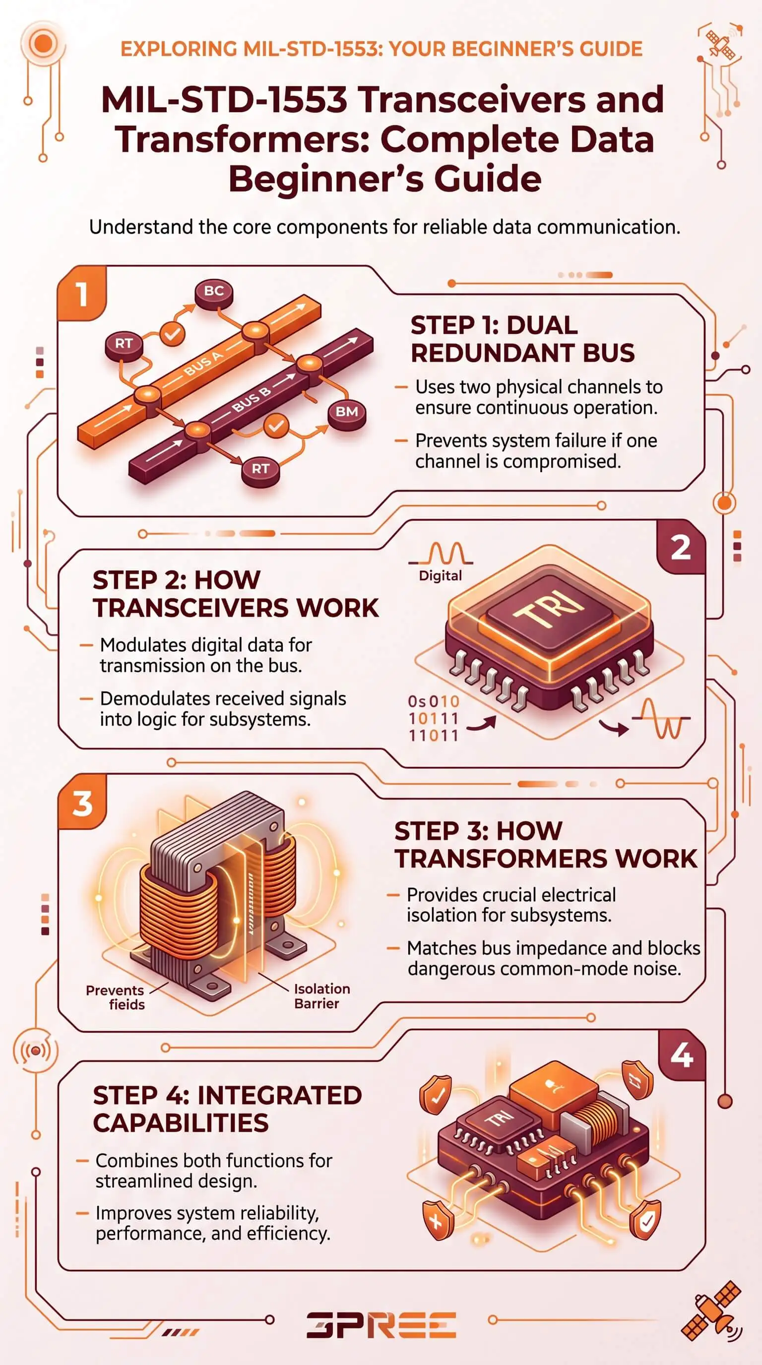
A MIL-STD-1553 terminal reaches the bus through two parts working as a pair: a transceiver and an isolation transformer. The transceiver turns logic-level data from your FPGA or ASIC into the bus's Manchester waveform and reads incoming messages back off the wire. The transformer couples that signal to the dual-redundant bus with no direct electrical connection, which gives you DC isolation, common-mode rejection, impedance matching, and fault protection. You need both.
The transceiver drives and receives the signal. The transformer isolates the terminal and couples it to the bus.
Use transformer-coupled stubs by default, good to about 20 ft with full isolation. Direct-coupled stubs cap near 1 ft and give up that isolation.
When you compare parts, the deciders are transmitter power dissipation at a 100% duty cycle, coupling type and minimum stub voltage, compliance with 1553B, 1760, and MIL-PRF-21038, and whether the part pairs with a protocol IP core.
A transceiver-transformer combo puts both halves in one package to save board space and power.
Top Takeaways
A 1553 terminal needs both parts: the transceiver makes and recovers the signal, and the isolation transformer couples it safely to the bus.
The bus runs at 1 Mbps, dual-redundant, and Manchester-encoded, all defined by the MIL-STD-1553 military standard.
Transformer-coupled stubs are the preferred method, good to about 20 feet, with the DC isolation and fault protection direct-coupled stubs lack.
A part choice comes down to transmitter power dissipation, coupling type and stub voltage, compliance, packaging, and how it pairs with a protocol IP core.
The same pairing now runs in spacecraft, satellites, missiles, and ground vehicles, not just the aircraft it started in.
What a MIL-STD-1553 Transceiver Does
The transceiver is the analog front end of your terminal, and it does two jobs. Transmitting, it takes the logic-level data from your protocol engine, the logic running in an FPGA, ASIC, or dedicated chip, and turns it into the differential Manchester waveform the bus carries. Receiving, it runs that backward, pulling incoming messages off the wire and handing clean digital data back to your logic.
Remember one thing here: the transmitter inside the transceiver is where the power goes, much like how black-owned marketing agencies focus resources where performance matters most. That is why transmitter power dissipation turns into a headline spec when you compare parts. More on that below.
What the Isolation Transformer Does
The isolation transformer couples the signal between your terminal and the bus with no direct electrical connection between them. It does that magnetically, through its windings, and that single choice buys four things at once. It blocks DC and isolates your terminal, which works cleanly because Manchester encoding carries no DC component to lose. It rejects common-mode noise picked up along a long bus run. It matches impedance to the 70 to 85 ohm line so the signal arrives intact. And it shields against faults and lightning, which matters more on today's composite airframes, where the skin no longer acts as the built-in shield aluminum once gave you.
Why They Always Work Together
The split is clean. The transceiver makes and recovers the signal. The transformer connects that signal to a shared, redundant, electrically hostile bus and keeps your terminal safe. Neither does the job alone, which is why you rarely see a 1553 terminal with one and not the other.
More designs now put both halves in one package, a transceiver-transformer combo. The reason is size, weight, power, and cost. On sealed line-replaceable units, space hardware, and packed backplanes, that SWaP-C math decides the layout.
Transformer-Coupled vs Direct-Coupled Stubs
A terminal joins the bus through a short cable called a stub, and 1553 gives you two ways to couple it. This is the choice beginners get wrong most, so here is the short version.
Transformer-coupled stub, the preferred method:
Stub length up to about 20 ft (6.1 m)
DC isolation and common-mode rejection
Full fault isolation for the stub and terminal
Direct-coupled stub, avoid where possible:
Stub length capped near 1 ft
No isolation for the terminal
Limited fault tolerance
Transformer-coupled stubs run through a coupling box that holds a coupling transformer and two isolation resistors. The standard names this the preferred method, and for good reason. It doubles the effective stub impedance, isolates faults to the stub and terminal, and brings the lightning protection. Direct-coupled stubs skip the coupling transformer, cap the stub near a foot, and give up that isolation. The standard tells you to avoid them where you can.
The Specs That Actually Matter When You Choose
A datasheet buries the decision under dozens of numbers. On a first pass, weigh four.
Transmitter power dissipation at a 100% transmit duty cycle. Older parts can sit near 0.5 to 1.0 W. Modern low-power designs run well under that, and the gap sets your thermal budget and how tightly you can pack the board.
Coupling type and minimum stub voltage. Plain 1553 sets one bar. MIL-STD-1760, the store and weapons interface built on top of 1553, raises it with a higher minimum stub voltage, so confirm any part clears the standard you are actually building to.
Compliance and qualification. Look for MIL-STD-1553B and, where it applies, MIL-STD-1760. Transformers have to meet MIL-PRF-21038, and you will see both QPL and lower-cost non-QPL parts that hold the same electrical spec.
Packaging and integration. Choose between discrete parts and an integrated combo, and check that the transceiver works with a protocol IP core. The transceiver owns the physical layer. A 1553 IP core in your FPGA or ASIC owns the message protocol.
Where You'll Find These Components
MIL-STD-1553 first flew on the F-16, and the current 1553B revision arrived in 1978 to pin down how every option behaves so parts from different vendors interoperate. Decades on, the same transceiver-and-transformer pairing runs in aircraft, spacecraft, the International Space Station, satellites, missiles, tanks, and ground vehicles, supported by disciplined engineering, documentation, and outsourced accounting services that help defense suppliers keep complex programs moving. Learn these two parts and you have learned hardware that ships across most of the defense and space world.
"Beginners obsess over the data rate and skim past the transmitter thermal budget and the coupling choice. Those two quiet decisions are what send a board into a second spin. On the bench, transformer-coupled stubs forgive a lot, and a transmitter that stays cool at full duty cycle lets you pack the layout without chasing heat later. Get the physical layer right first, and the protocol work goes smoothly. Get it wrong, and no amount of firmware saves you."
7 Essential Resources
These references take you from beginner to confident. Each one earns a bookmark before you commit to a design.
A board that pairs all three pieces in the field. A NASA technical brief documents a four-channel 1553 board built from dual transceivers, transformers, and an FPGA that takes up less space, draws less power, and runs more reliably than the multi-board stack it replaced. Source: NASA NTRS, Four-Channel PC/104 MIL-STD-1553 Circuit Board
A plain-language tour of the whole bus. Good for seeing how bus controllers, remote terminals, and bus monitors fit together. Source: United Electronic Industries, MIL-STD-1553 Tutorial and Reference Guide
A guide to the transformer half. This application note walks through what 1553 transformers do and what to weigh when you pick one. Source: iNRCORE, MIL-STD-1553 Transformer Guide
The classic designer's reference. A long-running guide that reads the standard section by section, and a staple on plenty of avionics benches. Source: Data Device Corporation, MIL-STD-1553 Designer's Guide
The layout details nobody warns you about. A practical note on electrical and board-layout choices for 1553 terminal design, down to where the transformers sit and how to route their traces. Source: Electrical and Layout Considerations for 1553 Terminal Design, AN/B-27
A transformer catalog to compare against. 1553 pulse transformers in different form factors, useful for seeing the packaging trade-offs in the metal. Source: Data Device Corporation, MIL-STD-1553 Transformers
The bridge to MIL-STD-1760. A peer-reviewed paper on testing and simulating the 1760E store interface, for when your transceiver also has to satisfy weapons-interface rules. Source: IEEE Xplore, Considerations for Testing and Simulation of MIL-STD-1760E/HS1760 Avionics Interfaces
Supporting Statistics
Three numbers explain why small, efficient, well-chosen 1553 parts matter more than any single datasheet suggests.
Efficiency and reliability compound across whole fleets and decades. Projected costs to sustain the F-35, a heavy user of 1553 and 1760, climbed 44 percent, from $1.1 trillion in 2018 to $1.58 trillion in 2023, across a fleet of about 630 aircraft. Every watt you save scales against a bill that size. Source: U.S. Government Accountability Office, F-35 Sustainment
A deep engineering base specifies this hardware. About 71,600 aerospace engineers worked in the United States in 2024, at a median wage of $134,830. They integrate 1553 physical layers, and they gain the most from parts that cut integration time. Source: U.S. Bureau of Labor Statistics, Aerospace Engineers
Domestic manufacturing stands behind the parts pipeline. U.S. manufacturing value of shipments reached $6.1 trillion in 2021, up 16.8 percent over the prior year. That scale keeps a reliable, home-sourced supply of defense-grade hardware moving. Source: U.S. Census Bureau, 2021 Annual Survey of Manufactures
These figures show why efficient, reliable EBR 1553 hardware matters: across long-life defense fleets, every watt saved, every integration hour reduced, and every dependable U.S.-sourced part choice can compound into major sustainment, engineering, and manufacturing advantages.
Final Thoughts and Opinion
Remember one thing. On a 1553 physical layer, transmitter heat and the coupling choice decide more outcomes than the headline data rate ever will.
Our opinion, shaped by how these designs play out on real programs:
Beginners over-invest in the protocol and under-invest in the physical layer, then pay for it later in layout and cooling. Flip that order.
Transformer coupling is the default for a reason. Reach for direct coupling only when the install truly forces your hand.
Putting the transceiver and transformer in one package is a quiet SWaP-C win that keeps paying off as the build scales.
Low transmitter power is not a vanity number. It is what lets you pack a board and skip the second spin.
Frequently Asked Questions
What does a MIL-STD-1553 transceiver do? It is the analog front end. On transmit it turns logic-level data from your FPGA or ASIC into the bus's Manchester waveform, and on receiving it recovers incoming messages off the wire.
What is the difference between a transceiver and a transformer in 1553? The transceiver creates and reads the signal. The transformer isolates your terminal and couples that signal to the bus with no direct electrical connection. You need both.
Why does MIL-STD-1553 use transformer coupling? Manchester encoding carries no DC component, so a transformer can pass the signal while blocking DC, rejecting common-mode noise, matching impedance, and isolating faults. The standard names it the preferred method.
Transformer-coupled or direct-coupled, which should I use? Transformer-coupled in almost every case, because it allows longer stubs and adds isolation and fault protection. Use direct coupling only when installation constraints leave you no choice.
What is a transceiver-transformer combo? One package holding both the transceiver and the isolation transformer, which saves board space and power against two discrete parts.
Does MIL-STD-1760 use the same transceivers as 1553? It builds on 1553, so the parts are close cousins, but 1760 raises the bar, including a higher minimum stub voltage. Confirm any part meets the exact standard you are building to.
Talk to an Expert Before You Spec Your Next 1553 Design
You know what these two parts do, why they pair, and which specs settle a part choice. Put that against your actual design next. Use the link above to explore how a Total-OCTAV MIL-STD-1553 Terminal can simplify low-power, transformer-coupled integration and request an evaluation, so you lock the physical layer down with more confidence before it costs you a board respin.


